Coordinate system programming
Whether a G-code program is generated from a 3D model with a tool such as Fusion 360 or Mastercam, or written by hand directly from work drawings, it is appropriate to bind the program coordinate system to the workpiece itself and not to the machine tool. For this purpose, Lotta typically has several work coordinate systems that can be preset and selected for use in the program at the desired stage. A typical use is to select the desired coordinate system at the beginning and keep it valid for the entire program execution time. But there is nothing to stop changing the coordinate system no matter how often during the program.
 |
Lotta's machine coordinate system (MACHINE COORDINATES) defines a box-like work area whose origin is fixed in the upper left corner of the box. The reason for choosing just this corner as the origin is practical; when driving all axes to the home position, the tool magazine is given maximum space to move during the change without colliding with the workpiece. It is possible to define a maximum of 6 work coordinate systems for the work area at the same time, which attach the origin of the coordinate system to a point in the machine coordinate system. Each work coordinate system can be freely defined independently of the others. |
Determining the origin of the work coordinate system Due to the way in which the length offset of Lotta tools is determined, the position of the origin of the work coordinate system must be determined exactly as described here. If this is not done, the tool length data stored in the tool table is not valid and may not be used in the program. So act as described here.
- Select the beeper as the tool. The beeper is not stored in the magazine, so this is done by manually removing the tool on the spindle and replacing it with the beeper.
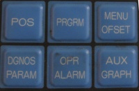
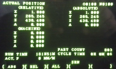
- Select the position information [POS] on the screen and confirm the display of the machine coordinates with the [ALL] soft key
- Manually guide the beeper ball ([MPG] is the most useful) close to the workpiece. Once you have decided which point will be the origin of the work coordinate system, guide the beeper ball to touch the origin alternately in the X and Y directions. Order does not matter in itself. Suppose you start with defining the X-direction. NOTE: Because the origin can be freely defined, the beeper can approach the point of contact from either the right or left. This causes a difference in the calculation of the X coordinate which will be taken into account later.
- When the ball touches the workpiece, it indicates the touch with an audible and visual signal. If you need a very accurate position coordinate, iterate the touch by scaling the handwheel movement smaller [100] -> [10] -> [1] until the desired touch accuracy is reached.
- Read the X coordinate of the contact from the X line of MACHINE coordinates.
- Compensates for the radius of the beeper ball. If you approached from the left, the contact is in a more positive direction by radius, so add 5,000 mm to the reading. If, on the other hand, you approached from the right, subtract the same amount.
- Switch offsets [MENU OFSET] and scroll [PAGE] to the desired work coordinate system
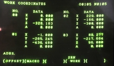
- Go to [CURSOR] for the desired coordinate system number (1 = G54, 2 = G55, etc. 'DO NOT select coordinate system 0!' )
- Now enter the newly measured and corrected reading as the X coordinate value using the number keys on the right side of the screen with the sequence [X] [nnn.nnn] [INPUT]. Make sure that the number you entered now appears in the correct location, ie as the X reading of the selected work coordinate system.
- Repeat the exercise by now directing the beeper ball in the Y direction to the origin and read the position and program the coordinate accordingly as a Y reading. The X / Y directions are now set.


The beeper cannot be used in the same way to determine the origin of the Z direction due to the tool length compensation used by Lotta. In fact, the origin of the Z-direction is determined very linearly by measuring its height from the table surface. The reading obtained is recorded directly in the work coordinate system as a Z-offset.
Until a dedicated instrument can be obtained, the easiest way to measure height is to use an angle iron and a caliper. Place the iron on the Z-plane where it is as horizontal as possible. Use a caliper to measure the height of the top surface of the iron from the table (watch out for debris and dents on the table!). Now when you subtract the thickness of the iron from the result (4,000 mm with Lotta's standard irons), the result is the Z coordinate directly and can be set in the same way as the X and Y coordinates above.
The coordinate system 0 displayed on the WORK COORDINATES screen is the so-called EXT or Extra coordinate system that behaves differently than other 1 ... 6. The offsets set in the EXT coordinate system are always valid regardless of which other coordinate systems are programmed for use. The determination of the length offsets of the Lotta tools is based on the use of the EXT Z offset with the length of the reference tool. THIS READING SHOULD NOT BE CHANGED unless it is intended to calibrate the calculation of the total length offset. If the reading changes, the length of each tool goes wrong immediately. So DO NOT MESS that figure!