Coordinate system programming
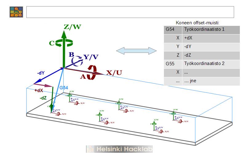
Whether a G-code program is generated from a 3D model with a tool such as Fusion 360 or Mastercam, or written by hand directly from work drawings, it is appropriate to bind the program coordinate system to the workpiece itself and not to the machine tool. For this purpose, Lota typically has several work coordinate systems that can be preset and selected for use in the program at the desired stage. A typical use is to select the desired coordinate system at the beginning and keep it valid for the entire program execution time. But there is nothing to stop changing the coordinate system no matter how often during the program.
Determining the origin of the work coordinate system Due to the way in which the length offset of Lota tools is determined, the position of the origin of the work coordinate system must be determined exactly as described here. If this is not done, the tool length data stored in the tool table is not valid and may not be used in the program. So act as described here.
- Select the beeper as the tool. The beeper is not stored in the magazine, so this is done by manually removing the tool on the spindle and replacing it with the beeper.
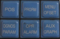
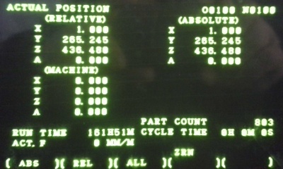
- Select the position information [POS] on the screen and confirm the display of the machine coordinates with the [ALL] soft key
- Manually guide the beeper ball ([MPG] is the most useful) close to the workpiece. Once you have decided which point will be the origin of the work coordinate system, guide the beeper ball to touch the origin alternately in the X and Y directions. Order does not matter in itself. Suppose you start with defining the X-direction. NOTE: Because the origin can be freely defined, the pager can approach the point of contact from either the right or left. This causes a difference in the calculation of the X coordinate which will be taken into account later.
- When the ball touches the workpiece, it indicates the touch with an audible and visual signal. If you need a very accurate position coordinate, iterate the touch by scaling the handwheel movement smaller [100] -> [10] -> [1] until the desired touch accuracy is reached.
- Read the X coordinate of the contact from the X line of MACHINE coordinates.
- Compensates for the radius of the beeper ball. If you approached from the left, the contact is in a more positive direction by radius, so add 5,000 mm to the reading. If, on the other hand, you approached from the right, subtract the same amount.
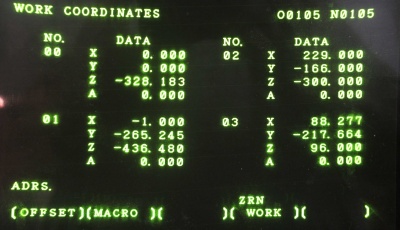
- Vaihda näyttöön offsetit [MENU OFSET] ja selaa [PAGE] näyttöön haluttu työkoordinaatisto
- Siirry [CURSOR] halutun koordinaatiston numeron kohdalle ( 1 = G54, 2 = G55 jne. ÄLÄ valitse koordinaatistoa 0!)
- Syötä äsken mitattu ja korjattu lukema nyt X-koordinaatin arvoksi käyttäen näytön oikealla puolella olevia numeronäppäimiä sekvenssillä [X] [nnn.nnn] [INPUT]. Varmista, että syöttämäsi luku näkyy nyt oikeassa paikassa, eli valitun työkoordinaatiston X-lukemana.
- Toista harjoitus ohjaamalla piipparin kuula nyt Y-suunnassa origoon ja lue asema sekä ohjelmoi koordinaatti vastaavalla tavalla Y-lukemaksi. X/Y-suunnat on nyt asetettu.
Piipparia ei voi samalla tavalla käyttää Z-suunnan origon määrittämiseen johtuen Lotan käyttämästä työkalujen pituuskompensoinnista. Itse asiassa Z-suunnan origo määritellään hyvin suoraviivaisesti mittaamalla sen korkeus pöydän pinnasta. Saatu lukema kirjataan suoraan työkoordinaatistoon Z-offsetiksi.
Kunnes saadaan hankittua tarkoitukseen pyhitetty mittalaite, on korkeuden mittaus helpointa käyttäen apuna särmärautaa ja työntömittaa. Aseta särmärauta Z-tason päälle kohtaan jossa se asettuu mahdollisimman vaakasuoraan. Mittaa työntömitalla särmäraudan yläpinnan korkeus pöydästä (varo roskia ja lommoja pöydässä!). Nyt kun vähennät tuloksesta särmäraudan paksuuden (4,000 mm Lotan vakioraudoilla) niin tulos on Z-koordinaatti suoraan ja se voidaan asettaa samoin kuin X- ja Y-koordinaatit edellä.
WORK COORDINATES -näytöllä näkyvä koordinaatisto 0 on ns. EXT eli Extra-koordinaatisto joka käyttäytyy eri tavoin kuin muut 1 ... 6. EXT-koordinaatistoon asetetut offsetit ovat aina voimassa riippumatta siitä, mitä muita koordinaatistoja on ohjelmoitu käytettäväksi. Lotan työkalujen pituusoffsettien määritys perustuu EXT Z-offsetin käyttöön siten, että siinä on referenssityökalun pituus. TÄTÄ LUKEMAA EI PIDÄ MENNÄ MUUTTAMAAN jollei tarkoitus ole kalibroida koko pituusoffsetin laskentaa. Mikäli lukema muuttuu, jokaisen työkalun pituus menee väärin saman tien. ÄLÄ siis sorki tuota lukua!


