Ero sivun ”Koulutus: Metallisorvi OPTIMUM” versioiden välillä
Ei muokkausyhteenvetoa |
(Added a summary and photos from the training session from the 22.11.2024 given by Paul) |
||
| (Yhtä välissä olevaa versiota toisen käyttäjän tekemänä ei näytetä) | |||
| Rivi 1: | Rivi 1: | ||
=Optimum metal lathe training and operation= | |||
Caution: | '''Some general guiding principles''' | ||
* Caution: Never change gears while the motor is on or the spindle is moving! | |||
* Engage gears and confirm they are engaged by rotating the spindle! | |||
* Always keep the tool clean during and after use: wipe the ways, remove chips, etc. | |||
* Every user has obligation to report if they notice something (and observe other users safe operation of the machine) | |||
'''A few gotchas and best practices''' | |||
Get a feel for the slack/play on the different axles: | * Get a feel for the slack/play on the different axles: The digital readout may give you a “false” sense of precision. | ||
* Always keep a tool in the tailstock | |||
* The top-slide should always be locked and in neutral position (flush with the front of the sled) | |||
* Locking of the carriage, cross-feed and top-slide: if something is binding, check why. There are hex set screws to lock those. | |||
* Drill chuck: must always be tighten with a tool | |||
* Jog Push Button for indicators only | |||
* Listen for headstock knocking sound | |||
* Tool post: always try to lock in place | |||
* Chuck wrench: always remove it from the chuck if not using | |||
* Whatever you do: work slowly enough so that you stay ahead of the machine, take your time, plan ahead when you stop the cut. | |||
* Threading: don't rely on lever position compared to the letters. Double check by doing a scratch pass and a check with a comb. | |||
* Avoid motor direction changes from forward to backward while the spindle is still turning, always use the break! Switching direction while the spindle is still turning may result in a voltage spike that trips the fuses (fuse box behind the CNC machine at the top of the outside wall) | |||
=Training / Material structure= | |||
The following is a rough outline of things that are discussed during a lathe training session. Use this as reference and refresher. '''These notes are no replacement for an actual training session!''' | |||
==Machine Operation== | |||
===1. Headstock=== | |||
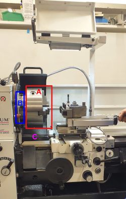
[[Tiedosto:Headstock.jpg|250px|oikea|pienoiskuva| The headstock with the 3 jaw (A) in the machine and spindle and sled safety covers up. The screws (A) engage the jaws, the 6 screws (B) allow for changing of the headstock]] | |||
* The most common headstock in use has 3 jaws that are auto-centering (may not be 100% center!): | |||
** The tightening screw tightens all three jaws simultaneously | |||
** There is a alternative set of jaw negative pieces, to change them unscrew the jaw screws all the way, then change the jaw pieces in order 1, 2, 3 as indicated on the jaws and stock | |||
* The lab also has a 4 jaw headstock with each jaw individually driven by an adjustment screw: | |||
** Allows more precise control | |||
** Allows holding e.g. square pieces | |||
* For changing the (heavy!) headstock protect the precision rails under the headstock with the wooden cover and head-shaped holder (under the table opposite of the machine) | |||
** Always change back to the 3 jaw headstock after you have finished | |||
<div style="clear: both"></div> | |||
===2. Gearbox=== | |||
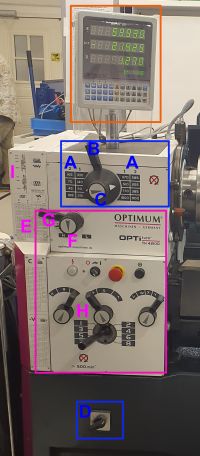
[[Tiedosto:Speed-gears.jpg|200px|pienoiskuva|The left-hand side of the lathe: DRO atop (orange), speed selection (blue), autofeed selection (pink)]] | |||
'''General notes:''' | |||
* Never change speed (blue) or autofeed (pink) while the spindle is turning (as indicated by the icon right of the speed selection table) | |||
* While changing gears, rotate the spindle to hear and feel the gear engage | |||
* If a very low speed is selected (e.g. 45, 70, 90) the spindle may be quite hard to turn by hand | |||
* All gears are mechanical, except for the motor speed switch (D) | |||
* Functionality: The motor drives the speed gear, which in turn drives the autofeed when engaged | |||
'''Speed selection (blue)''' | |||
* Selecting the spindle speed (blue) is a multi-step process: | |||
** Pick a speed from the table (A) | |||
** Use the big top lever (B) to select the row in the table | |||
** Use the middle knob (C) to select left or right side of the table | |||
** Select motor speed 1 or 2 from the switch (D) to select the 1 or 2 column in the table, respectively | |||
** e.g. the spindle speed in the image is 510: right side of the table, second row, column 1 | |||
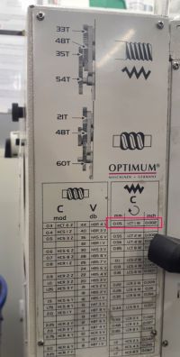
[[Tiedosto:Autofeed-speed.jpg|200px|pienoiskuva|An example autofeed selection: To get a autofeed movement of 0.05mm/0.002in per spindle revolution, set the gears to position LCT 1 W]] | |||
'''Autofeed selection (pink)''' | |||
* Consult your desired feed rate from the tables at E, which are (left to right, top to bottom): Worm screw, general machining, threading (metric), threading (imperial); each table has the travel distance per spindle revolution as its left-most column | |||
* From the selected row reference the gear letter combination (see image): | |||
* Turn knob F and the A-C, R-T and V-Z as well as the 1-8 levers | |||
* Knob F in mid position between (as in the image) the autofeed is disengaged entirely | |||
* Knob G selects the threading direction, top being the standard thread direction towards the stock, bottom away from it | |||
* Note: Some ''uncommon selections'' require a physical change of gears as indicated by the image on the top left; to change those cogwheels (blue metal box) take of the cover on the left side of the machine to access the gears | |||
<div style="clear: both"></div> | |||
===3. Carriage and Cross sled=== | |||
* | '''General notes''' | ||
* Unlike the gear side of the machine, the sled side controls (levers, wheels) are intended to be used while the lathe is running | |||
* The machine '''will not turn on if the safety covers of spindle or sled are open''' (the indicator light on the gear panel is not illuminated) | |||
* The machine movement has no built-in safety stops or movement limits — at all time '''be aware of the dimensions of work piece, spindle and sled movements''' and make sure things that shouldn't touch won't! | |||
'''General manual operation''' | |||
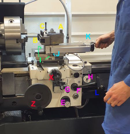
[[Tiedosto:Lathe_Sled.jpg|450px|pienoiskuva|Most of the sled components colored by functionality: A-C tool holder and adjustment, E-H autofeed controls, I cross feed sled angle locking, J-K fine Z axis control and locking pin, '''L main gear'''. Both safety covers of spindle and carriage are open in the image.]] | |||
When both protective covers (spindle and carriage) are closed, lever L turns on the motor. Down position is natural ''forward'' for the motor, upward allows ''reversing''. | |||
The main carriage controls are the big wheels (Z) and (X). Both wheels are free spinning as a safety precaution, and they to be pushed in to engage to control their respective axis. A second sled control (K) is usually locked flush with the main sled. It is locked with a tiny hexagonal head bolt is tucked away under J. It can be used with the tool moving at an angle off the z axis and the work piece by changing the tool head angle by opening the bolts (I) when the retracted. If you use the this sled, be extra mindful of the chuck and make sure to '''lock it in straight position and flush with the carriage'' front after use. | |||
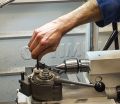
The tool (B) is fixed in the head with bold (A). The tool can be inserted in the tool holder at any angle. The tool height can adjusted by (C) by opening the locking nut, then using the adjustment screw. To adjust the height of the tool tip to be ''reasonably close to center'' of the spindle use the tail stock with the holding tip to reference center. | |||
<gallery mode="traditional"> | |||
Tiedosto:Tool-y-locking-pin.jpg|Tool in holder parallel to x direction | |||
Tiedosto:Tool-diagonal.jpg|Tool in holder at an angle | |||
Tiedosto:Tool-height-adjustment.jpg|Tool height adjustment using the tailstock for center reference | |||
</gallery> | |||
'''Autofeed controls on the sled''' | |||
When using the autofeed note that if the autofeed gear is in neutral (between H and L on the gear side) the autofeed cannot engage no matter what. | |||
Keep in mind that the autofeed speed is liked to the spindle rotation: '''Changing the spindle rotation speed will directly relate to autofeed speed!''' | |||
The main controls for the autofeed are lever G and E. G has a neutral middle position (in image), and can be engaged to autofeed either in z-axis (up and right) or x-axis (down) direction. The push/pull knob E inverts the direction of autofeed. '''It is advisable to always test the autofeed speed and directions with the sled way from the spindle''' to be sure of movement directions and speed. | |||
Lever F engages and disengages the threading shaft. In turning operation the lever is disengaged (up position) as seen in the picture. To use the autofeed for threading the lever if is engaged downwards to start moving the sled in z-axis. The dial H is a timing dial to make repeated thread cuts that align. | |||
===4. Tailstock=== | |||
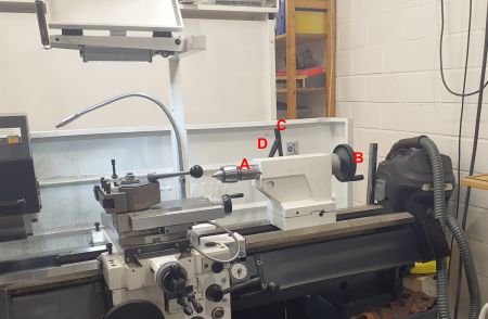
[[Tiedosto:Optimum-tailstock.jpg|450px|pienoiskuva|oikea|The tailstock components: An engage tool (A), z-axis adjustment control (B), movement locking lever (C) and spinning locking lever (D)]] | |||
The tailstock inserts are fixed in the holder simply by their conical morse taper shape. To remove a tailstock insert (center pin, drill chuck, etc.) use the wheel (C) retract all the way, which will free the tool. Some of the inserts have a lip at the end indicating orientation, as well as a "window" in the stock that allows inserting a tool to free it. '''Be careful not to insert any tools which cannot be freed!''' | |||
The tail carriage has two levers to restrict movement. The right most lever (C) locks the carriage in place along the z-axis. The left lever (D) locks the z-axis control wheel. | |||
===5. Break=== | |||
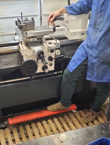
[[Tiedosto:Optimum-break.jpg|450px|pienoiskuva|oikea|The main break of the lathe (red foot lever).]] | |||
The foot break does two things: '''Cuts the motor power''' and '''engages a physical break''' to stop the spindle from spinning. | |||
Further note that: | |||
* The break can be activate while the machine is in gear | |||
** When doing so, disengage the main lever and re-engage it to start the machine again | |||
** Releasing the break will never turn the machine back on | |||
* Other ways of "turning off" the machine like the emergency power off button, or the main motor engaging lever on the right of the sled, do not stop the spindle from turning, they just cut the power | |||
===6. DRO (Digital Position Readout=== | |||
* The DRO provides basic movement information along each axis | |||
* To reset a certain axis, select the axis (orange button), set the new value (e.g. 0), then Enter | |||
* The R/D button switch (and indicate) radius vs diameter mode (!) | |||
<div style="clear: both"></div> | |||
---- | |||
=Tools usage= | |||
The lab has a copy of the "Black Book" with lots of general tool, material and speed information. | |||
==Tools Types== | |||
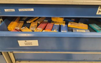
[[Tiedosto:Lathe-bits.jpg|350px|pienoiskuva|oikea|Supply drawer with replacement tips]] | |||
Most Lab tools are equipped with replaceable carbide tips. Generally, these tips rely on speed, rather than cutting sharpness, so operate better at higher speeds. | |||
Note that different tips are used for different materials. For example softer metals like Aluminium require special tips that cannot be used with harder metals. | |||
===Facing=== | |||
===Boring=== | |||
===Parting=== | |||
===Tapping=== | |||
===Drilling=== | |||
===Sanding and Polishing=== | |||
===Reaming=== | |||
==Feed & Speed== | |||
===Carbide vs HSS=== | |||
==Materials== | |||
===Steel=== | |||
===Aluminium=== | |||
===Copper=== | |||
===Brass=== | |||
===Polymers=== | |||
==Coolant, Lubrication== | |||
[[Tiedosto:Tiedosto:Optimum-coolant.jpg|450px|pienoiskuva|oikea|The adjustable coolant sprout]] | |||
The lathe has a coolant/lubricant delivery hose. '''It is messy, you have been warned.''' | |||
* | * To engage coolant turn on the water tap switch on the gear panel | ||
* The actual sprout has a water flow control | |||
* The system is closed so re-uses the water from the tank | |||
* Normal use does not require doing anything to the liquid tank | |||
---- | |||
=Machine Maintenance and Adjustment= | |||
==Cleaning== | |||
After general use make sure to clean the general surfaces in and around the machine. '''Pay extra attention to keeping the precision machined sled tracks free of any debris'''. There is a vacuum cleaner to the right of the lathe. Empty the metal shavings under the machine if they are overflowing. | |||
=Ways Lubrication= | |||
=Chuck change= | |||
=Chips removal from the bed= | |||
Use the large metal hook to pull metal shreds from the bed and place them in the solid metal bin. | |||
Nykyinen versio 23. marraskuuta 2024 kello 12.33
Optimum metal lathe training and operation
Some general guiding principles
- Caution: Never change gears while the motor is on or the spindle is moving!
- Engage gears and confirm they are engaged by rotating the spindle!
- Always keep the tool clean during and after use: wipe the ways, remove chips, etc.
- Every user has obligation to report if they notice something (and observe other users safe operation of the machine)
A few gotchas and best practices
- Get a feel for the slack/play on the different axles: The digital readout may give you a “false” sense of precision.
- Always keep a tool in the tailstock
- The top-slide should always be locked and in neutral position (flush with the front of the sled)
- Locking of the carriage, cross-feed and top-slide: if something is binding, check why. There are hex set screws to lock those.
- Drill chuck: must always be tighten with a tool
- Jog Push Button for indicators only
- Listen for headstock knocking sound
- Tool post: always try to lock in place
- Chuck wrench: always remove it from the chuck if not using
- Whatever you do: work slowly enough so that you stay ahead of the machine, take your time, plan ahead when you stop the cut.
- Threading: don't rely on lever position compared to the letters. Double check by doing a scratch pass and a check with a comb.
- Avoid motor direction changes from forward to backward while the spindle is still turning, always use the break! Switching direction while the spindle is still turning may result in a voltage spike that trips the fuses (fuse box behind the CNC machine at the top of the outside wall)
Training / Material structure
The following is a rough outline of things that are discussed during a lathe training session. Use this as reference and refresher. These notes are no replacement for an actual training session!
Machine Operation
1. Headstock
- The most common headstock in use has 3 jaws that are auto-centering (may not be 100% center!):
- The tightening screw tightens all three jaws simultaneously
- There is a alternative set of jaw negative pieces, to change them unscrew the jaw screws all the way, then change the jaw pieces in order 1, 2, 3 as indicated on the jaws and stock
- The lab also has a 4 jaw headstock with each jaw individually driven by an adjustment screw:
- Allows more precise control
- Allows holding e.g. square pieces
- For changing the (heavy!) headstock protect the precision rails under the headstock with the wooden cover and head-shaped holder (under the table opposite of the machine)
- Always change back to the 3 jaw headstock after you have finished
2. Gearbox
General notes:
- Never change speed (blue) or autofeed (pink) while the spindle is turning (as indicated by the icon right of the speed selection table)
- While changing gears, rotate the spindle to hear and feel the gear engage
- If a very low speed is selected (e.g. 45, 70, 90) the spindle may be quite hard to turn by hand
- All gears are mechanical, except for the motor speed switch (D)
- Functionality: The motor drives the speed gear, which in turn drives the autofeed when engaged
Speed selection (blue)
- Selecting the spindle speed (blue) is a multi-step process:
- Pick a speed from the table (A)
- Use the big top lever (B) to select the row in the table
- Use the middle knob (C) to select left or right side of the table
- Select motor speed 1 or 2 from the switch (D) to select the 1 or 2 column in the table, respectively
- e.g. the spindle speed in the image is 510: right side of the table, second row, column 1
Autofeed selection (pink)
- Consult your desired feed rate from the tables at E, which are (left to right, top to bottom): Worm screw, general machining, threading (metric), threading (imperial); each table has the travel distance per spindle revolution as its left-most column
- From the selected row reference the gear letter combination (see image):
- Turn knob F and the A-C, R-T and V-Z as well as the 1-8 levers
- Knob F in mid position between (as in the image) the autofeed is disengaged entirely
- Knob G selects the threading direction, top being the standard thread direction towards the stock, bottom away from it
- Note: Some uncommon selections require a physical change of gears as indicated by the image on the top left; to change those cogwheels (blue metal box) take of the cover on the left side of the machine to access the gears
3. Carriage and Cross sled
General notes
- Unlike the gear side of the machine, the sled side controls (levers, wheels) are intended to be used while the lathe is running
- The machine will not turn on if the safety covers of spindle or sled are open (the indicator light on the gear panel is not illuminated)
- The machine movement has no built-in safety stops or movement limits — at all time be aware of the dimensions of work piece, spindle and sled movements and make sure things that shouldn't touch won't!
General manual operation
When both protective covers (spindle and carriage) are closed, lever L turns on the motor. Down position is natural forward for the motor, upward allows reversing.
The main carriage controls are the big wheels (Z) and (X). Both wheels are free spinning as a safety precaution, and they to be pushed in to engage to control their respective axis. A second sled control (K) is usually locked flush with the main sled. It is locked with a tiny hexagonal head bolt is tucked away under J. It can be used with the tool moving at an angle off the z axis and the work piece by changing the tool head angle by opening the bolts (I) when the retracted. If you use the this sled, be extra mindful of the chuck and make sure to 'lock it in straight position and flush with the carriage front after use.
The tool (B) is fixed in the head with bold (A). The tool can be inserted in the tool holder at any angle. The tool height can adjusted by (C) by opening the locking nut, then using the adjustment screw. To adjust the height of the tool tip to be reasonably close to center of the spindle use the tail stock with the holding tip to reference center.
Autofeed controls on the sled
When using the autofeed note that if the autofeed gear is in neutral (between H and L on the gear side) the autofeed cannot engage no matter what.
Keep in mind that the autofeed speed is liked to the spindle rotation: Changing the spindle rotation speed will directly relate to autofeed speed!
The main controls for the autofeed are lever G and E. G has a neutral middle position (in image), and can be engaged to autofeed either in z-axis (up and right) or x-axis (down) direction. The push/pull knob E inverts the direction of autofeed. It is advisable to always test the autofeed speed and directions with the sled way from the spindle to be sure of movement directions and speed.
Lever F engages and disengages the threading shaft. In turning operation the lever is disengaged (up position) as seen in the picture. To use the autofeed for threading the lever if is engaged downwards to start moving the sled in z-axis. The dial H is a timing dial to make repeated thread cuts that align.
4. Tailstock
The tailstock inserts are fixed in the holder simply by their conical morse taper shape. To remove a tailstock insert (center pin, drill chuck, etc.) use the wheel (C) retract all the way, which will free the tool. Some of the inserts have a lip at the end indicating orientation, as well as a "window" in the stock that allows inserting a tool to free it. Be careful not to insert any tools which cannot be freed!
The tail carriage has two levers to restrict movement. The right most lever (C) locks the carriage in place along the z-axis. The left lever (D) locks the z-axis control wheel.
5. Break
The foot break does two things: Cuts the motor power and engages a physical break to stop the spindle from spinning.
Further note that:
- The break can be activate while the machine is in gear
- When doing so, disengage the main lever and re-engage it to start the machine again
- Releasing the break will never turn the machine back on
- Other ways of "turning off" the machine like the emergency power off button, or the main motor engaging lever on the right of the sled, do not stop the spindle from turning, they just cut the power
6. DRO (Digital Position Readout
- The DRO provides basic movement information along each axis
- To reset a certain axis, select the axis (orange button), set the new value (e.g. 0), then Enter
- The R/D button switch (and indicate) radius vs diameter mode (!)
Tools usage
The lab has a copy of the "Black Book" with lots of general tool, material and speed information.
Tools Types
Most Lab tools are equipped with replaceable carbide tips. Generally, these tips rely on speed, rather than cutting sharpness, so operate better at higher speeds.
Note that different tips are used for different materials. For example softer metals like Aluminium require special tips that cannot be used with harder metals.
Facing
Boring
Parting
Tapping
Drilling
Sanding and Polishing
Reaming
Feed & Speed
Carbide vs HSS
Materials
Steel
Aluminium
Copper
Brass
Polymers
Coolant, Lubrication
The lathe has a coolant/lubricant delivery hose. It is messy, you have been warned.
- To engage coolant turn on the water tap switch on the gear panel
- The actual sprout has a water flow control
- The system is closed so re-uses the water from the tank
- Normal use does not require doing anything to the liquid tank
Machine Maintenance and Adjustment
Cleaning
After general use make sure to clean the general surfaces in and around the machine. Pay extra attention to keeping the precision machined sled tracks free of any debris. There is a vacuum cleaner to the right of the lathe. Empty the metal shavings under the machine if they are overflowing.
Ways Lubrication
Chuck change
Chips removal from the bed
Use the large metal hook to pull metal shreds from the bed and place them in the solid metal bin.
